Traditionally the vane test method is used in conjunction with fluid rotary drilling or hollow-stem auger drilling. Soil sampling, such as with thin wall sampling tubes is often combined with vane testing, since knowledge of the nature of the soil in which that vane test is done is of great importance for the assessment of the test. The soil sampling procedure can also be used to provide a hole through which the vane tester can be lowered.
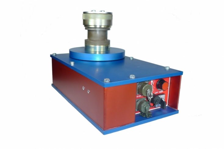
The electric field vane tester is available in two versions; one with a vane protection shoe and protection tubes (in accordance with ISO 22476-9, ASTM D2573-08 and Eurocode 7) and a system without any of these protections. Both versions feature the same electrical instrument for applying and recording the torque and slip-coupling; a state-of-the-art vane measuring instrument which is the heart of the vane tester set. It is to be mounted on the push-and-pull yoke of a CPT penetrometer rig.
This measuring instrument is equipped with a high precision torque sensor piloted by an electronic control system controlling the testing procedures and automating the acquisition of all data with high accuracy (< 1% of FS). The shear loading curve is recorded digitally on the attached PC computer (not included) by means of the vane data acquisition software.
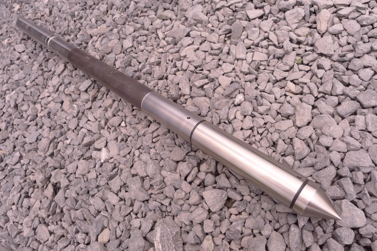
The down-hole equipment consists of vanes, a slip-coupling, extension rods and casing tubes. The Eurocode electrical vane apparatus comes with casing tubes to avoid most skin friction and a vane protection shoe enabling to push the vane directly into the soil without having to make a borehole or similar. A slip-coupling is mounted between the extension rods and the vane in order to be able to measure the friction between the extension rods and the casing tubes. The standard electrical field vane apparatus comes without casing and protection shoe and can therefore only be used in boreholes. A similar slip-coupling as in the Eurocode model is used for measuring the skin friction along the rods.
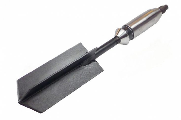
The vanes are of high quality nickel-chromium steel and specially designed to penetrate the soil easily with minimum disturbance. Their measuring range is 0-50, 0-100 and 0-200 kPa, see below. The standard model vanes have a tapered lower end to improve penetration while the Eurocode model vanes have rectangular blades. Other vane dimensions can be supplied upon request.
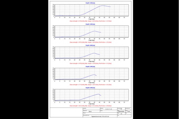
For all vane tests, the shear loading is recorded with the measured torque as function of the applied rotation angle. During a test, the electric vane test instrument rotates the extension rods from the surface. Down-hole, the torque is absorbed during the first 15 degrees of rotation by the slip-coupling on top of the vane. Thereafter, the torque is transmitted to the vane. The speed of rotation is set manually. The recording of the torque, measured with strain gauges, is done every half degree with the vane data acquisition software, installed on a PC computer.
When editing the test data, the rod friction is deducted from the maximum applied torque and given the dimensions of the vane used, the undrained shear strength is calculated, displayed and stored by the software. The stored shear strength values are then displayed as a function of depth according to the Swedish Geotechnical Society (SGF) format.
With the standard model, between tests in a sounding, the vane is further pressed into the ground with the extension rods which run through the chuck of the vane instrument. The Eurocode model comes with a vane protection shoe and casing tubes. After each test, the vane is pulled back up and locked in its protection shoe. The vane protection shoe is then pushed deeper into the ground by means of the casing tubes.
The rotational speed can be adjusted from 0.1° per second up to 15° per second, while the resulting data are recorded every half degree. According to the chosen vane dimension, the software monitors the actual torsion and limits the applied force when the shear strength reaches 100kN/m2. The shape of the curve provides a control of the correctness of the test and an indication of the nature of the soil.
The torque required to turn the rods is first registered, then the total torque applied to both the rods and the vane until failure is registered. The difference between these values is used to calculate the shear strength of the soil. The figures are stored in an individual file for each test. The measured values are graphically visualised in real-time and plotted against the rotational angle. Simultaneously all measured values, sample number and time are logged in a separate file.
Upon completion of the undrained shear test, the user can easily start a remould test. On a key-stroke the electronic controls will turn the vane 5 revolutions at a speed of 15° per second. To prevent damage the maximum torque during remould is limited to 50%. After these 5 revolutions the system returns to the preset turning speed and will log the residual shear strength. If required, the user can repeat the remould operation, e.g. when the initial 5 revolutions revealed to be insufficient. The results of both undrained and residual shear strength are presented in the same graph.
The rotation speed or time to failure varies in the different vane test standards. The Eurocode 7 says that the vane has to rotate at a constant speed between 0.1 and 0.2 degree per second (i.e. 6 – 12 degrees per minute). The speed can therefore be adjusted with a rotation speed regulator or potentiometer on the panel of the vane instrument and can be monitored on the screen display of the software.
Please consider one of the following standards when doing a field vane test:
- Eurocode ENV 1997-3, part 3
- ASTM STP 1014 on Vane Shear Strength Testing in Soils (1988)
- ASTM D2573-08
- ISO 22476-9