skip to Main Content

Nearshore Cone Penetration Testing

Nearshore CPT (top push technique) is not as difficult as it might seem. Most CPT companies do already have most of the necessary equipment in house, but lack the know-how. The purpose of this manual is to give an indication of the procedures of nearshore cone penetration testing. The help of an experienced CPT-operator remains indispensable at the initial phase of a nearshore project.

In case of nearshore cone penetration testing (also referred to as over-water, inshore or marine CPT) the specifications of the equipment, the operation and the procedures to follow differ slightly from land testing. This document presents the most likely solutions for nearshore CPT in relatively shallow waters, i.e. up to approx. 25 meter.

In general, considerable penetration depths below the seabed can be reached, even if the water depth is 25 m. This last value is about the limit, since for larger water depths the jack-up rigs become very expensive, or in case of a floating barge the environmental influences can become too substantial.

First and most important is to determine what kind of working platform is most suitable for the project. This can either be a jack-up rig or a floating barge. In general, a jack-up is best since tidal variation, flow and waves have no effect on the readings. Furthermore the risk of breaking rods (lost and damaged equipment) is considerably lower.
In some cases a floating barge can be used provided that:

  • The area is reasonably protected from environmental influences
  • Tidal variations are non-existent
  • Waves are minor
  • The barge is well secured by anchors or spud piles

The CPT tests are normally carried out through a moon-pool in the deck of the jack-up rig or barge. If a moon-pool is not available, it is also possible to work from a platform alongside the jack-up rig or barge. The latter is from the safety point-of-view not recommendable.

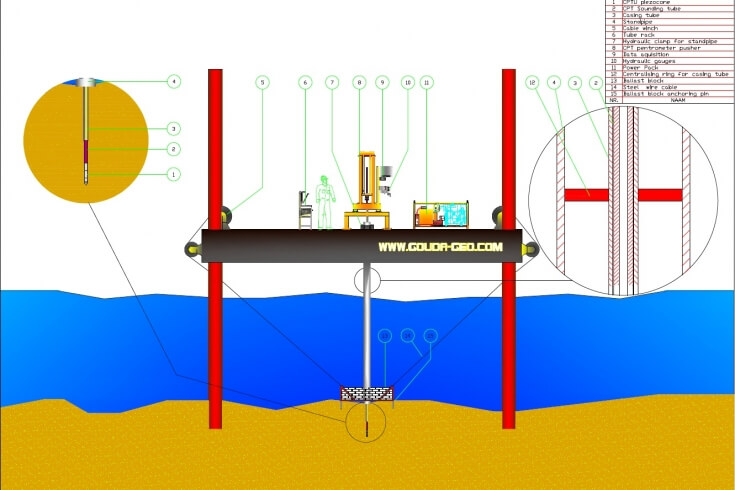
When working over water, a “standpipe” is to be used at all times. This pipe shall act as the major casing through which all other tubes will run, such as the CPT casing, the CPT sounding tubes and the possible drill-string. The design of the standpipe is crucial; it determines the success or failure of a nearshore CPT project.

Over the years we have learned that an awful lot of pushing force can be lost due to friction on the string of sounding tubes. Staggering losses of pushing force of 90% and more have been observed. This was all due to the insufficient design of the standpipe.

When the free play between the exterior of the CPT sounding tubes and the inside of the supporting casing is too large, the string of sounding tubes is allowed too much space and tends to buckle. This will result extremely high forces on the inside of the supporting casing and lead to tremendous loss of pushing force.

Other causes that can lead to loss of pushing force are the inflow of material at the shoe (which creates a plug) and the fact that the standpipe is not placed perfectly vertical.

The standpipe has to be lowered by means of a crane or alike and fixed into the seabed in such a manner that the current has no influence on the standpipe. This can be achieved by pushing the shoe of the standpipe into the seabed or by using a ballast block at the bottom end of the standpipe.

In general the standpipe sinks into the seabed as a result of its own weight. This has to be verified by comparing the length of the standpipe with the water depth and the elevation of the deck above water level.

If the standpipe is not firmly in place, one risks that the standpipe will be displaced by tidal influences or waves, making it impossible to continue the CPT test. A secure fixing of the standpipe to the deck of the working platform is also very important. This can be done by means of hydraulic holding clamp, that prevents the standpipe of sliding further (e.g. by its own weight) into the seabed.

The best moment to place the standpipe is at neap tide when the influence of the tide is minimum. The standpipe is for obvious reasons be placed as vertical as possible.

It is recommended to equip the standpipe with 2 inclinometer sensors to monitor the verticality of the standpipe. The shoe of the standpipe is to be equipped with 4 lifting eyes (in NESW orientation), which make it possible to adjust the verticality of the standpipe using 4 simple winches on the deck.

Certainly near the seabed it is recommended to opt for an open design of the standpipe so that material can flow freely in and out of the standpipe and the risk of clogging is avoided. This makes the standpipe also less susceptible for the underwater current.

A lifting ring with lifting eye(s) is required to lift the standpipe in and out of the moon pool.

It is advisable to design the ballast block such, that it can be made heavier by adding more ballast in case of heavy current. Pins are recommended at the bottom to avoid lateral movement over the seabed (the pins will sink more easily into the seabed).

The standpipe is to be designed such that it can be used for both CPT testing and over-drilling.

The standpipe should compose of elements of different length making it feasible to build a standpipe having the right length since water depths might vary from spot to spot.

Always opt (if possible) for a flange connection. It is much easier to connect two pipes that way and it results in a more ridged standpipe. Use flush connections only in case of a small diameter moon pool.

Standard CPT casing tubes are 1 meter long and have an inner diameter (ID) of 39 mm and an outer diameter (OD) of 55 mm. As can be seen, the tolerance between the OD of the CPT sounding tubes (36 mm) and the ID of the casing tubes (39 mm) is small, which is essential in order to provide sufficient lateral support of the CPT sounding tubes and prevent buckling.

The OD and ID of the standpipe are not defined. They depend on water depth, local conditions (flow, waves) and availability. Spacers are normally welded on the CPT casing tubes at 2 m intervals, again with a small tolerance between the spacer OD and the ID of the standpipe. The maximum OD of the standpipe is limited by the ID of the moon pool and the on-board lifting capacity (weight).

For nearshore CPT testing we always advise to use a 15 cm² (piezo-) cone in order to anticipate possible high load on the cone. Since the 44 mm CPT sounding tubes are about 2.2 times stronger, we recommend these as well. To overcome the friction on the string of CPT sounding tubes inside the standpipe, we recommend to use a 350 kN CPT penetrometer pusher instead of a 200 kN rig.

If a client wishes, the Gouda-Geo design team can make the design of a standpipe for your project(s) based on water depth, current, seabed material, seabed “landscape”, type of jack-up barge, on-board lifting capacity, moon pool diameter, type of CPT test, etc.

The 350 kN stand-alone CPT penetrometer set for nearshore testing is an economical rig with full CPT testing capabilities. It is because of its design and possible extra’s very suitable for cone penetration testing in relatively shallow waters, i.e. up to approx. 25 meter. The CPT set is suitable for both electrical and mechanical CPT testing, but in daily
practice only used for electrical CPT.

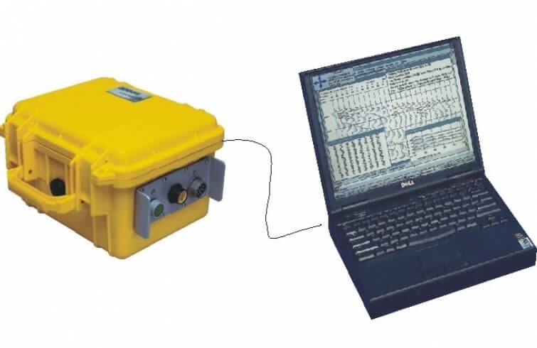
The CPT penetrometer set comprises a 350 kN 2-cylinder CPT penetrometer pusher, a diesel-hydraulic or an electric-hydraulic power-pack with load-sensing pump, manually operated valves, mounting frame, stainless-steel housing for datalogger and computer, etc.

A hydraulic CPT penetrometer pusher with a pushing capacity of 350 kN, comprising 2 vertical hydraulic cylinders, simultaneously operated with a stroke of 1350 mm. A thrust block connects the two cylinders and is capable of driving and pulling the CPT sounding tubes and casing tubes into and out of the ground.

A hydraulic control unit, mounted on a console near the CPT penetrometer pusher, allows the operator to control all functions. The unit comes complete with a guiding tubes, to be applied between the penetrometer and ground level.

  • Max. pushing force: 350 kN
  • Max. pulling force: 450 kN
  • Unloaded speed up: 105 mm/sec
  • Unloaded speed down: 145 mm/sec
  • CPT testing speed: 20 mm/sec
  • Weight: Approx. 740 kg

The CPT penetrometer pusher will be powered by an electric-hydraulic power-pack. The power-pack comprises a powerful electric motor (22 kW) incorporated in the burry frame.

The motor drives a Linde load-sensing pump. The power-pack features a phase sequence relay, which checks the correct direction of field rotation. When the green indicator light on the switch box lights up, the phase sequence is correct. Large hydraulic oil reservoir with an effective filtering system.

  • Dimensions (L x W x H): 120 x 80 x 161 cm
  • Weight: Approx. 785 kg
  • Power supply: 400 Vac, 50 Hz, clockwise field of rotation (41 A)
  • Power: 22 kW @ 1470 RPM
  • Utility class: S1 (continuous)
  • Pump: Linde, load-sensing
  • Hydraulic tank: 340 litre

The 350 kN stand-alone CPT penetrometer set can be supplied with the following accessories and CPT equipment:

  • Hydraulic catch, integrated in the support beam of the CPT penetrometer pusher, that holds the tubes when working e.g. over water or when retrieving tubes out of very soft soils
  • Hydraulic gripping system for quick lowering and retrieving of CPT sounding tubes and casing tubes (only in combination with a clamping device for automated pulling and pushing of CPT sounding tubes and casing tubes)
  • Stainless steel rack with foldable trays for the storage of CPT tubes
  • Stainless steel housing for storage data acquisition system and laptop
  • 2-dimensional level (type “bull’s eye”), adjustable, make Kern
  • Toolbox with toolset for maintenance and repair
  • Electrical CPT system with standard or piezocone
  • CPT sounding tubes
  • Casing tubes and cutting shoe
  • Manuals in English, Dutch, German, French, Spanish or Portuguese

In all cases, the weight (i.e. the reaction force) of the jack-up rig or barge and thus the reaction force of the rig should be in line with the scheduled pushing capacity needed. Furthermore, it is strongly recommended to apply a penetrometer pusher equipped with a hydraulic catching clamp for holding the casing tubes and the CPT sounding tubes whilst lowering them through the standpipe or retrieving them. An automatic push and pull clamp equipped with an additional hydraulic gripping system functions perfectly in combination with this catching clamp to drive and lift the CPT casing and CPT sounding tubes.

In case of electrical CPT testing, typically lengths of 10 m for the CPT cables are applied. This is both economical and practical, since CPT casing and CPT tubes must be handled in turns. It is therefore easier to have the possibility to disconnect the CPT cables.

  1. Install the standpipe in such a way, that flow or waves have no effect on it anymore
  2. Lower CPT casing tubes (55/39 x 1000 mm), if applicable provided with spacers, to the seabed
  3. Lower the CPT cone by means of the CPT sounding tubes to the seabed and start to penetrate (a friction reducer cannot be used in this case)
  4. Stop penetrating as soon as the soil becomes slightly more consistent
  5. Push the casing tubes to a depth just above the cone
  6. Continue CPT testing again to a secure depth and push the casing tubes behind
  7. Casing is not required anymore as soon as the cone has reached a substantially supportive layer
  1. Install the standpipe to such a depth, that flow or waves have no effect on it anymore
  2. Lower the cone by means of the CPT sounding tubes to the seabed and start the test
  3. In case of soft top soils the CPT cone will advance by the weight of the sounding string for a couple of meters
  4. Once the cone no longer advances (or does not advance at all), apply minimum pushing force until the cone is securely standing in the soil
  5. Disconnect the nearest extension connector of the CPT sounding cable
  6. Lower CPT casing tubes (55/39 x 1000 mm), if applicable provided with spacers, to a depth just behind the friction reducer of the cone
  7. Re-connect the extension connector again and proceed CPT testing by penetrating the cone and CPT sounding tubes into the soil
  8. Stop penetrating as soon as the soil becomes slightly more consistent
  9. Push the casing tubes to a depth just above the friction reducer of the cone
  10. Continue CPT testing again to a secure depth and push the casing tubes behind
  11. Casing is only required to a depth where a substantially supportive layer starts

NOTE:    Nearshore CPT testing with friction reducer is not hearty recommended for it requires some luck that the CPT cone hits the seabed more-or-less exactly in the centre of the standpipe. If you’re unfortunate the CPT sounding tubes get damaged by the casing or penetrate the soil under a severe angle.

Over-drilling could be required when targeted CPT testing depth can’t be reached with the available pushing force generated by the penetrometer pusher. If maximum pushing capacity is reached prior to reaching the targeted end-depth of the CPT, special measures have to be taken to proceed the CPT beyond that point. For over-drilling we suggest the following sequence of operation:

  1. Remove first of all the CPT casing
  2. Retract the CPT cone and the string of CPT sounding tubes
  3. Move the CPT pushing equipment aside
  4. Remove all other casing and support tubes except for the standpipe
  5. Position the drill-rig over the moon-pool and lower the drill-string through the standpipe till the seabed
  6. Drill into the seabed till the desired depth. We recommend either cable percussion or rotary flush
  7. Lift the drill-string from the standpipe, remove the drill-rig, and re-insert the casing and support tubes
  8. Re-install the CPT penetrometer pusher
  9. Re-install the CPT cone and the string of CPT sounding tubes till the drilling depth
  10. Re-install the CPT casing also to the drilling depth
  11. Continue the CPT testing procedure from that point on

Repeat this procedure until the desired testing depth has been reached.

In conclusion, nearshore cone penetration testing requires some additional investments in boundary CPT equipment (i.e. standpipe and casing) and one should realize that these CPT tests are much more time consuming compared to on-land CPT’s. An experienced operator can do up to 3 nearshore cone penetration tests per day.

Gouda-Geo can assist by bringing you in contact with experienced CPT operators, who have performed nearshore CPT’s as described above under various circumstances worldwide.

Search